Getting to Know SONET/SDH SFP+ Transceivers
Plesiochronous Digital Hierarchy (PDH) system was the earliest stand used to transport phone calls and data over the same fiber. With the increasing demand of phone calls and data traffic, SONET/SDH are then introduced to replace PDH system to transport the data without synchronization problems. As you can see, SONET/SDH SFP+ transceivers have been widely used in the market. This post will give a brief analysis on SONET/SDH SFP+ transceivers.
SONET (Synchronous Optical Networking) and SDH (Synchronous Digital Hierarchy) are multiplexing protocols that transfer multiple digital bit streams over optical fiber with lasers or light-emitting diodes (LEDs). SONET and SDH are widely used methods today for very high speed transmission of voice and data signals across the numerous world-wide fiber-optic networks. SONET is the standard used in the United States and Canada, and SDH in the rest of the world. The two are largely equivalent. Although the SONET standards were developed before SDH, it is considered a variation of SDH because of SDH’s greater worldwide market penetration.
We often find SONET/SDH SFP transceiver like Cisco OC-3/STM-1 LR-1 SFP 1310nm 40km IND DOM. What does OC-3/STM-1 mean? OC-3c (Synchronous Transport Signal 3, concatenated) is the basic unit of SONET. Depending on the system, OC-3 is also known as STS-3 (when the signal is carried electrically). STM-1 (Synchronous Transport Module, level 1) is the basic unit of framing in SDH, which operates 155.52 Mbit/s. OC-3c and STM-1 have the same high-level functionality, frame size, and bit-rate.
10 Gigabit Ethernet (10GbE) means the Ethernet network runs at 10 Gigabit per second. The 10 Gigabit Ethernet defines two PHY (Physical Layer) types: a local area variant (LAN PHY) with a line rate of 10.3125 Gbit/s, and a wide area variant (WAN PHY) with the same line rate as OC-192/STM-64 (9,953,280 Kbit/s).
10GbE provided the potential for an Ethernet solution aligned with the data rate of OC-192 backbone. It’s the first time in Ethernet history that no additional speed matching equipment would be required to link with the WAN. A seamless end-to-end Ethernet network can be built with less money. But the question is how to balance the compatibility with the installed base of OC-192 equipment while still meeting the economic feasibility criteria of the P802.3ae Task Force in defining the 10GE WAN PHY. To solve this problem, an OC-192 frame format is provided to support only the SONET overhead features required for fault isolation. This simplification avoids unnecessary functions and cost.
In order to make sure that WAN PHY optics would benefit from the high volumes and low cost of Ethernet, the serial 1310 nm and 1550 nm transceiver modules were kept the same as the LAN PHY. Since the 1310 nm and 1550 nm transceiver modules are designed for up to 10km and 40 km links respectively, they will inter-operate with OC-192 transceiver modules for 1310 nm and 1550 nm over intermediate reach, respectively.
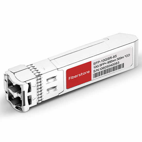
FS.COM supplies OC-192/STM-64 SFP+ for short reach (SR-1, VSR) , intermediate reach (IR-2) and long reach (LR-2) applications. These SFP+ modules are compatible with the SONET/SDH and ATM standards. For more details, please visit the website at fs.com.
Introduction to DWDM Technology
As the most popular WDM technology, DWDM (Dense wavelength-division multiplexing) revolutionized data transmission technology by increasing the capacity signal of embedded fiber. This increase means that the incoming optical signals are assigned to specific wavelengths within a designated frequency band, then multiplexed onto one fiber. By providing channel spacings of 50 GHz (0.4 nm), 100 GHz (0.8 nm) or 200 GHz (1.6 nm), several hundreds of wavelengths can be placed on a single fiber. DWDM takes advantage of the operating window of the Erbium Doped Fibre Amplifier (EDFA) to amplify the optical channels and extend the operating range of the system to over 1500 kilometers. The following picture shows the operation of a DWDM system.
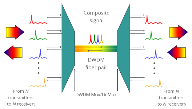
A typical DWDM system is composed of transmitter, receiver, optical amplifier, transponder, DWDM multiplexer and DWDM demultiplexer. They allow DWDM system to interface with other equipment and to implement optical solutions throughout the network, complying with the ITU channel standards.
- Optical transmitters/receivers
Transmitters in DWDM systems provide the source signals which are then multiplexed. Multiple optical transmitters are used as the light sources in a DWDM system. We can also utilize a transceiver to replace transmitters and receivers to achieve the same purpose. Usually a DWDM transceiver applied in DWDM network can reach a transmission distance of up to 120km. - Optical amplifiers
Optical amplifiers (OAs) boost the amplitude or add gain to optical signals passing on a fiber by directly stimulating the photons of the signal with extra energy. They are “in-fiber” devices. OAs amplify optical signals across a broad range of wavelengths. This is very important for DWDM system application. Erbium-doped fiber amplifiers (EDFAs) are the most commonly used type of in-fiber optical fibre. - Transponders
Transponders are designed to convert optical signals from one incoming wavelength to another outgoing wavelength suitable for DWDM applications. Transponders are optical-electricaloptical (O-E-O) wavelength converters. Within a DWDM system, a transponder converts the client optical signal back to an electrical signal (O-E) and then performs either 2R (reamplify, reshape) or 3R (reamplify, reshape, and retime) functions.
A transponder is located between a client device and a DWDM system. From left to right, the transponder receives an optical bit stream operating at one particular wavelength (1310 nm). The transponder converts the operating wavelength of the incoming bitstream to an ITU-compliant wavelength. It transmits its output into a DWDM system. On the receive side (right to left), the process is reversed. The transponder receives an ITU-compliant bit stream and converts the signals back to the wavelength used by the client device. - DWDM Multiplexers and Demultiplexers
Multiple wavelengths (all within the 1550 nm band) created by multiple transmitters and operating on different fibers are combined onto one fiber by way of an optical multiplexer. The output signal of an optical multiplexer is referred to as a composite signal. At the receiving end, a demultiplexer separates all of the individual wavelengths of the composite signal out to individual fibers. The DWDM demultiplexers are capable of distinguishing each wavelength without crosstalk. The individual fibers pass the demultiplexed wavelengths to as many optical receivers. Typically, mux and demux (transmit and receive) components are contained in a single enclosure. Optical mux/demux devices can be passive. Component signals are multiplexed and demultiplexed optically, not electronically, therefore no external power source is required.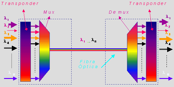
As occurs with many new technologies, the potential ways in which DWDM can be used are only beginning to be explored. Already, however, the technology has proven to be particularly well suited for several vital applications.
DWDM is ready made for long-distance telecommunications operators that use either point–to–point or ring topologies. The sudden availability of 16 new transmission channels where there used to be one dramatically improves an operator’s ability to expand capacity and simultaneously set aside backup bandwidth without installing new fiber.
This large amount of capacity is critical to the development of self-healing rings, which characterize today’s most sophisticated telecom networks. By deploying DWDM terminals, an operator can construct a 100% protected, 40 Gb/s ring, with 16 separate communication signals using only two fibers.
DWDM is the clear winner in the backbone. It was first deployed on long-haul routes in a time of fiber scarcity. Then the equipment savings made it the solution of choice for new long-haul routes, even when ample fiber was available. While DWDM can relieve fiber exhaust in the metropolitan area, its value in this market extends beyond this single advantage. Alternatives for capacity enhancement exist, such as pulling new cable and SONET overlays, but DWDM can do more. What delivers additional value is DWDM’s fast and flexible provisioning of protocol- and bit rate-transparent, data-centric, protected services, along with the ability to offer new and higher-speed services at less cost.
Introduction to DWDM Technology
As the most popular WDM technology, DWDM (Dense wavelength-division multiplexing) revolutionized data transmission technology by increasing the capacity signal of embedded fiber. This increase means that the incoming optical signals are assigned to specific wavelengths within a designated frequency band, then multiplexed onto one fiber. By providing channel spacings of 50 GHz (0.4 nm), 100 GHz (0.8 nm) or 200 GHz (1.6 nm), several hundreds of wavelengths can be placed on a single fiber. DWDM takes advantage of the operating window of the Erbium Doped Fibre Amplifier (EDFA) to amplify the optical channels and extend the operating range of the system to over 1500 kilometers. The following picture shows the operation of a DWDM system.

A typical DWDM system is composed of transmitter, receiver, optical amplifier, transponder, DWDM multiplexer and DWDM demultiplexer. They allow DWDM system to interface with other equipment and to implement optical solutions throughout the network, complying with the ITU channel standards.
- Optical transmitters/receivers
Transmitters in DWDM systems provide the source signals which are then multiplexed. Multiple optical transmitters are used as the light sources in a DWDM system. We can also utilize a transceiver to replace transmitters and receivers to achieve the same purpose. Usually a DWDM transceiver applied in DWDM network can reach a transmission distance of up to 120km. - Optical amplifiers
Optical amplifiers (OAs) boost the amplitude or add gain to optical signals passing on a fiber by directly stimulating the photons of the signal with extra energy. They are “in-fiber” devices. OAs amplify optical signals across a broad range of wavelengths. This is very important for DWDM system application. Erbium-doped fiber amplifiers (EDFAs) are the most commonly used type of in-fiber optical fibre. - Transponders
Transponders are designed to convert optical signals from one incoming wavelength to another outgoing wavelength suitable for DWDM applications. Transponders are optical-electricaloptical (O-E-O) wavelength converters. Within a DWDM system, a transponder converts the client optical signal back to an electrical signal (O-E) and then performs either 2R (reamplify, reshape) or 3R (reamplify, reshape, and retime) functions.
A transponder is located between a client device and a DWDM system. From left to right, the transponder receives an optical bit stream operating at one particular wavelength (1310 nm). The transponder converts the operating wavelength of the incoming bitstream to an ITU-compliant wavelength. It transmits its output into a DWDM system. On the receive side (right to left), the process is reversed. The transponder receives an ITU-compliant bit stream and converts the signals back to the wavelength used by the client device. - DWDM Multiplexers and Demultiplexers
Multiple wavelengths (all within the 1550 nm band) created by multiple transmitters and operating on different fibers are combined onto one fiber by way of an optical multiplexer. The output signal of an optical multiplexer is referred to as a composite signal. At the receiving end, a demultiplexer separates all of the individual wavelengths of the composite signal out to individual fibers. The DWDM demultiplexers are capable of distinguishing each wavelength without crosstalk. The individual fibers pass the demultiplexed wavelengths to as many optical receivers. Typically, mux and demux (transmit and receive) components are contained in a single enclosure. Optical mux/demux devices can be passive. Component signals are multiplexed and demultiplexed optically, not electronically, therefore no external power source is required.
As occurs with many new technologies, the potential ways in which DWDM can be used are only beginning to be explored. Already, however, the technology has proven to be particularly well suited for several vital applications.
DWDM is ready made for long-distance telecommunications operators that use either point–to–point or ring topologies. The sudden availability of 16 new transmission channels where there used to be one dramatically improves an operator’s ability to expand capacity and simultaneously set aside backup bandwidth without installing new fiber.
This large amount of capacity is critical to the development of self-healing rings, which characterize today’s most sophisticated telecom networks. By deploying DWDM terminals, an operator can construct a 100% protected, 40 Gb/s ring, with 16 separate communication signals using only two fibers.
DWDM is the clear winner in the backbone. It was first deployed on long-haul routes in a time of fiber scarcity. Then the equipment savings made it the solution of choice for new long-haul routes, even when ample fiber was available. While DWDM can relieve fiber exhaust in the metropolitan area, its value in this market extends beyond this single advantage. Alternatives for capacity enhancement exist, such as pulling new cable and SONET overlays, but DWDM can do more. What delivers additional value is DWDM’s fast and flexible provisioning of protocol- and bit rate-transparent, data-centric, protected services, along with the ability to offer new and higher-speed services at less cost.
10G SFP+ or 10GBASE-T for 10GbE Network?
In order to cater for the increasing need for speed and bandwidth in telecommunication networks, high speed Ethernet has never stopped developing, from earlier 100M, 1G, 10G, to 40G and 100G. The standard for 10 Gigabit Ethernet (IEEE802.3ae) was ratified in 2002. Many subscribers find it difficult to make a choice between fiber and copper. This article will introduce the media options for 10GbE network and make a comparison between them.
- 10G SFP+ Modules
SFP+ module supports both fiber optic cables and DAC (direct attach cable). It delivers a wide variety of 10GbE Ethernet connectivity options for data center, enterprise wiring closet, and service provider transport applications. But it has the limitations that will prevent the media from moving to every server. - SFP+ Direct Attach Cable
SFP+ cable is designed for 10GbE access layer interconnection in data center. It includes direct attach copper cables and active optical cables. DAC is a lower cost alternative to fiber, but it can support limited transmission distance and it’s not backward-compatible with existing GbE switches. DAC requires the purchase of an adapter card and requires a new top of rack (ToR) switch topology. DAC is more expensive than structured copper channels, and cannot be field terminated. - 10GBASE-T SFP
10GBase-T SFP enables 10GbE connections with unshielded or shielded twisted pair cables over distances up to 100 meters. 10GBase-T technology appears as SFP is not compatible with twisted pair cabling system typically used in data centers. With 10GBase-T SFP, the migration from 1GbE to 10GbE can be easily achieved.
Latency
Low latency becomes so important since the adoption of private cloud applications increases. It’s beneficial for ensuring fast response time and reducing CPU (center processing units) idle cycles so that improve data center efficiency.As to 10GBASE-T SFP, the physical connection (PHY) standard uses block encoding to transport data across the cable without errors. The block encoding requires a block of data to be read into the transmitter PHY, a mathematical function run on the data before the encoded data are sent over the link. It happens the same on the receiver side. This standard specifies 2.6 microseconds for the transmit-receive pair, and the block size requires latency to be less than 2 microseconds. While 10G SFP+ applies simplified electronics without encoding, and common latency is around 300 nanoseconds per link.
You may think that two microseconds are not high. But what if a TOR infrastructure where traffic is passing 4 hops to reach the destination? 10.4-microsecond delay will be caused when using 10GBASE-T SFP. The following table tells details about the latency of SFP+ cable, 10G SFP+ (eg. Finisar FTLX1471D3BCV) and 10GABSE-T SFP for different number of links.
| Number of Links | SFP+ Cable Latency | 10G SFP Latency | 10GBASE-T SFP Latency |
| 1 | 0.3 | 0.1 | 2.6 |
| 2 | 0.6 | 0.2 | 5.2 |
| 3 | 0.9 | 0.3 | 7.8 |
| 4 | 1.2 | 0.4 | 10.4 |
| 5 | 1.5 | 0.5 | 13.0 |
| 6 | 1.8 | 0.6 | 15.6 |
From the above table, it shows that the latency of 10GBASE-T SFP is the highest. As network links grow, the latency turns to be higher. It’s known that the lower latency, the faster the network speed. High latency in the data center infrastructure results in delays in CPU and application works, therefore limiting data center efficiency and increasing operational costs.
Power Consumption
Power consumption is also one of the important factors to be considered in data centers. Engineers are sensitive to power consumption and find a way to seek the lowest possible power consumption technologies. It’s said that every watt of power consumed, typically two additional watts are needed for cooling.10GBase-T components today require anywhere from 2 to 5 watts per port at each end of the cable depending on the distance of the cable. But 10G SFP+ requires about 0.7 watt regardless of distance. The figure below compares the power consumption of three media options of 10GbE Ethernet.
Lower power consumption and lower latency makes 10G SFP+ well suited for large high-speed supercomputing applications where latency is a critical factor and where high port counts can add up to significant power savings.
QSFP+ Direct Attach Copper Cables for EX Series Switches
Quad small form-factor pluggable plus (QSFP+) direct attach copper (DAC) cables are cables with QSFP+ module at one end or both ends. They are suitable for in-rack connections between QSFP+ ports of EX Series switches. They are suitable for short distances of up to 10 meters, making them ideal for highly cost-effective networking connectivity within a rack and between adjacent racks. This article will introduce EX Series switches and QSFP+ DAC for EX Series switches.
EX Series switches deliver scalable port densities and carrier-proven high availability features that consolidate legacy switch layers, helping to reduce capital and operational expenses and advance the economics of networking. For example, the EX 4200 series Ethernet switches with Virtual-Chassis technology, deliver the same Gigabit Ethernet (GbE) and 10GbE port densities as traditional chassis-based switches, but at one-eighth the footprint and less than one third the cost. The EX Series switches are right-sized for campus, data center and remote office environments and feature many of the same carrier-class hardware and software architectures found in core routers that were purpose-built to support the convergence of data, voice, and video onto a single always-on network.
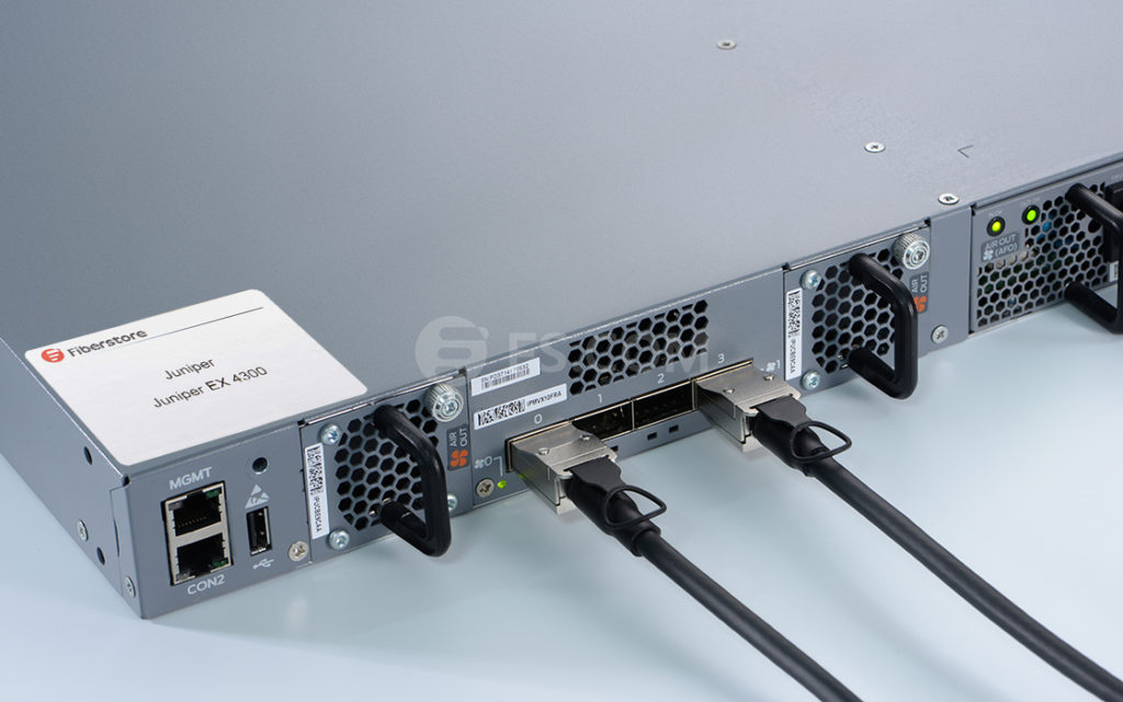
By alleviating the cost, complexity and risk associated with legacy switch infrastructures, the EX Series switches enable high-performance businesses to deploy a high-performance network infrastructure based on three key tenets – operational simplicity, carrier-class reliability, and integration and consolidation – to enable ubiquitous access to strategic assets, reduce network downtime and enhance overall security to shared assets across the extended enterprise.
QSFP+ direct attach copper (DAC) cable is hot-removable and hot-insertable. QSFP+ DAC mainly has two kinds. One is a cable that connects directly into two QSFP+ modules, one at each end of the cable. The cables use integrated duplex serial data links for bidirectional communication and are designed for data rates up to 40 Gbps. The other is a breakout cable consisting of a QSFP+ transceiver on one end and four SFP+ transceivers on the other end. The QSFP+ transceiver connects directly into the QSFP+ access port on the QFX Series device. The cables use high-performance integrated duplex serial data links for bidirectional communication on four links simultaneously. The SFP+ links are designed for data rates up to 10 Gbps each.
The following table describes the software support for QSFP+ passive DAC cable lengths on EX Series switches for Junos OS releases.
|
SWITCH |
SOFTWARE SUPPORT ADDED |
DAC MODEL NUMBER |
|---|---|---|
|
EX44300 switches |
Junos OS for EX Series switches, Release 13.2X51-D15 or later |
|
|
EX4300 switches |
|
|
|
EX4550 switches |
|
|
QSFP+ direct attach copper cables can provide cost-effective and reliable 40G speed connections for EX Series switches with distances reaching up to 10 meters. As the leading fiber optical manufacturer in China, FS.COM offers various types of QSFP+ DAC with low cost but high performance. Apart from the above-mentioned, FS.COM offers Cisco QSFP+ breakout cable as well. All these DACs are with 100% compatibility and can be customized according to your particular needs.
1000Base-T SFP Modules for Gigabit Ethernet
Gigabit Ethernet technology is an extension of the 10/100-Mbps Ethernet standard, providing a raw data bandwidth of 1000 Mbps while maintaining full compatibility with the installed base of over 70 million Ethernet nodes. A Gigabit Ethernet is imperative for two reasons: faster systems and faster backbones. Gigabit Ethernet has the potential for low-cost products, freedom of choice in selecting the products, interoperability, and backward compatibility. Gigabit Ethernet supports existing applications, network operating systems, and network management; it requires a minimal learning curve for Ethernet network administrators and users. These investment preservation and risk minimization aspects are what make Gigabit Ethernet so attractive. With the development of Ethernet systems and the growing capacity of modern silicon technology, embedded communication networks are playing an increasingly important role in embedded and safety critical systems.
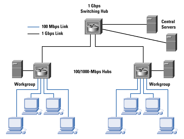
A known type of data communication device is a small form factor pluggable (SFP) module. Typically, the SFP module plugs into an interface slot in a circuit board populated with other communication devices used in an Ethernet-based system. The SFP module includes a second serial interface, interconnected with the circuit board slot, and a first serial interface, coupled to a serial link, such as a copper or fiber link, for communicating with remote link partners. The serial link, coupled with the first serial interface, may be a 10/100/1000 Base-T copper link, or a fiber link, for example. The SFP module also offers several significant advantages over its predecessor, the GBIC (Gigabit Interface Converter), including lower cost, lower power, and smaller size. Thus, with the SFP form factor, fiber Gigabit systems may be developed featuring similar port densities as copper-only systems using RJ-45 connectors.
The SFP transceiver Multi-source Agreements (MSA) document puts forward a specification for the development of optical SFP modules based on IEEE 802.3z, the Gigabit Ethernet Standard. Specifically, the MSA calls out 1000Base-X Physical Coding Sub-layer (PCS) which supports full-duplex binary transmission at 1.25 Gbps over two copper wire-pair SerDes (Serializer/Deserializer). Transmission coding is based on the ANSI Fiber Channel 8B/10B encoding scheme.
1000Base-X makes no provision for running at slower speeds. Thus, network device ports utilizing SFPs are dedicated to operating on fiber links at speeds of 1000 Mbps. However, more than 85% of office space inside buildings is category 5 copper. Thus, ports designed to use optical SFPs can not make use of this existing cabling.
For example, a customer may require a network device, such as a router, having both optical ports for long distance connections and RJ-45 copper ports for connecting to local devices. It is often the case that not all optical ports provided on a router are needed at a given time. However, with conventional SFPs these optical ports cannot be utilized to connect with local devices connected by standard copper cabling or operating at speeds lower than 1000 Mbps. But with a 1000BASE-T copper SFP transceiver, the customer could use their existing copper cabling infrastructure instead of replacing the infrastructure. Here are two good examples of 1000BASE-T SFP transceivers, the Finisar FCLF-8521-3 compatible 1000BASE-T SFP copper transceiver and Cisco Linksys MGBT1 compatible 1000BASE-T SFP copper transceiver from FS.COM. Both of them are designed for 100m reach over Cat 5 UTP cable with RJ-45 interface and support max data rate of 1000Mbps.
The 1000BASE-T copper SFP transceiver offers a flexible and simple method to be installed into SFP MSA compliant ports at any time with no interruption of the host equipment operation. It enables for seamless integration of fiber with copper LAN connections wherever SFP interface slots can be found. Such system is economical, it saves time, offers flexibility and eliminates the necessity for replacing entire devices once the customers have to change or upgrade fiber connections and you will benefit so much from it.
Why Choose Fiber Optic Cables in AV Systems?
As audio and video technologies continue to evolve, AV systems are continuously challenged with supporting high resolution video, audio, and control signals. The combination of light and glass presents some unique properties that give AV professionals powerful tools in common AV applications. A fiber optic cable can be used to send high resolution video, audio, and control signals on a single fiber over 30 km (18.75 miles), and avoids the risk of signal loss or degradation, ground loop hums, and electrical interference. Because transmission of content is inherently secure and immune to outside interference, fiber applications are favored in government, military, and medical environments. This article will mainly introduce four advantages of the installation of fiber optic cables in AV applications.
Fiber optic cables are low-loss channels that enable transmission of high resolution video, audio, and control signals over long distance. Losses in fiber optic cables are 0.2 to 3.5 dB/km, compared to 60 dB/km for legacy RG6 coaxial cable at 100 MHz. The low-loss nature of single-mode fiber cables can enable transmission of WQXGA 2560x1600 video signals up to 30 km. Due to these advantages, fiber optic cables are widely used in campuses, sports stadiums and large office buildings, etc. Besides, installing fiber optic cables with extremely high bandwidth can ensure that future applications can be addressed with today’s fiber installations.
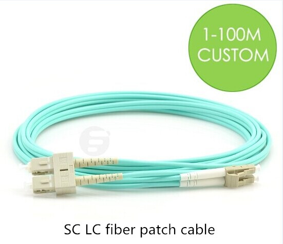
Fibers consume very little space in conduit and cable trays, and are easy to pull. For example, duplex fiber optic cable can transmit high resolution video signals but is only a fraction of the size of a coaxial cable. Because of fiber optic cables’ small size, the installation is much easier especially in medical applications where there is often insufficient space for thicker cables. Besides, today’s field termination kits make fiber easier to terminate than other types of cabling. Simply striping, cleaving, and inserting fibers into fiber optic connectors, you can get a high quality, reliable splice in minutes. And you can also choose pre-terminated fiber cables, such as LC patch cable or SC LC fiber patch cable (as shown below). The connectors you specify are pre-terminated for you, and the fiber cables you specify are cut to the proper length that you need. When the installation is over, you can just plug and play fiber optic system.
Unlike copper cables, fiber optic cables are largely comprised of glass, which does not carry electrical current, radiate energy, or produce heat or sparks. So they can be safely installed in hazardous environments, such as oil refineries, mining operations, or chemical plants, without the danger of generating an electrical spark. Applications using sensitive electronics, such as medical environments, also benefit from the lack of electrical emissions with fiber optic systems. Fiber optic applications have helped the medical field advance tremendously over the past decade. They not only allow the physician to see inside specific areas of the body and perform surgery on hard-to-reach areas, but also provide a quicker and more accurate analysis of blood work.
Fiber optic systems may provide a lower total cost of ownership over the life of the system when compared to a coaxial or twisted pair solution. In copper systems, old cables need to be removed and new cables to be pulled for each system upgrade. While fiber optic cables with high bandwidth can be reused through multiple system upgrades. In addition, fiber optic cables typically consume less power and produce less heat than copper wires, thus reducing both electrical and cooling costs. Moreover, fiber optic systems can be monitored and serviced from the main equipment room without disrupting activities in work areas.
Fiber optic cables provide unique advantages in an AV system, particularly in secure and long distance applications. Choosing the proper cable depends upon the number of fibers required, installation location, topology, and the overall design of the system. Cable constructions are available for both indoor and outdoor applications to provide a solution for virtually any AV system.
