Twisted Pair Cabling Overview
Nowadays, fiber optic cable becomes one of the most popular mediums for both new cabling installations and upgrades, including backbone, horizontal, and even desktop applications. Though fiber offers a number of advantages over copper, copper still has a space in telecommunication networks, for example, direct attach copper cables, like HP JG081C 10G SFP+ direct attach copper cable or Cisco QSFP+ breakout cable (Cisco QSFP-4SFP10G-CU5M). As one of the oldest types of cable ever invented, twisted pair cable was first developed in 1881. Since then, it has been widely deployed for telephone line networks. Nowadays, the application of twisted pair cables has been extended worldwide mainly for outdoor land lines offering telephone voice service.
Twisted pair cable is a kind of copper wiring made by putting two separate insulated wires together in a twisted pattern and running them parallel to each other. It is widely used in different kinds of data and voice infrastructures. To reduce crosstalk or electromagnetic induction between pairs of wires, two insulated copper wires are twisted around each other. Each connection on twisted pair requires both wires. Twisted pair can offset electromagnetic interference (EMI) from external sources to stop degrading the performance of circuit.
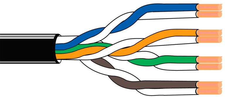
There are two twisted pair types: shielded and unshielded. A shielded twisted pair (STP) has a fine wire mesh surrounding the wires to protect the transmission; an unshielded twisted pair (UTP) does not. Shielded cable is used in older telephone networks, as well as network and data communications to reduce outside interference.
Also, different standards of twisted pair cables are specified into various categories as Cat 1, Cat 2, Cat 3, Cat 4, Cat 5/5e, Cat 6/6a, Cat 7/7a, Cat 8/8.1/8.2. And the following text will briefly introduce several categories.
Cat 5 twisted pair cable is often used for structured cabling of computer networks. It is available to 10/100 Mbps speeds at up to 100 MHz bandwidth. However, it is now considered to be obsolete and replaced by Cat 5e (enhanced). Cat 5e is one the most commonly used twisted pair cables now. The biggest distinction between Cat 5 and Cat 5e is that Cat 5e has a lower crosstalk and its transmitting speed can reach up to 1000 Mbps.
As a substitute of Cat 5/5e, Cat 6 twisted pair cable is applied to Gigabit Ethernet and other network physical layers. Cat 6 supports up to 10 Gbps speed at 250 MHz. When used for 10GBASE-T applications, Cat 6 has a reduced maximum length from 37 to 55 meters. Cat 6a (augmented) twisted pair cable has been evolved to perform at up to 500 MHz, thus the maximum cable distance is longer than Cat 6 of up to 100 meters.
Cat 7 is the standard for twisted pair cabling used for 1000BASE-T and 10GBASE-T networks. It provides performance of up to 600 MHz with a maximum length of 100 meters. Cat 7a (augmented) twisted pair cable has a higher frequency of 1000 MHz. Results show that Cat 7a may be possible to support 40 GbE or even 100 GbE at a very short length.
Cat 8 is the USA standard specified by ANSI/TIA while Cat 8.1 and Cat 8.2 are specified by ISO/IEC for global application. All these three kinds of Cat 8 twisted pair cables are used for 25GBASE-T and 40GBSE-T at the maximum frequency of up to 2 GHz. Except Cat 8 adopts Cat 8 links, Cat 8.1 uses class I links and Cat 8.2 uses class II links. The key difference between class I and class II is that class II allows three different styles of connectors that are not compatible with one another, or with the RJ45 connector.
Twisted pair cables have been classified into different grades called categories. Higher categories are more expensive than lower ones, but most of the cost is actually spent on labor force for installing the cables. And twisted pair cables under Cat 5 are not recommended now. Higher categories are the future trends for network cabling.
How to Properly Handle Optical Fiber?
Fiber optic cables have been more and more widely used in all kinds of applications. You can use fiber optic jumper cables to connect end devices or network hardware to the structured cabling system and one popular type of fiber optic jumper cables, MPO cable, is a good solution for your high density applications. The technique to handle optical fiber can have a significant impact on the functionality and reliability of a fiber optic cable. The cost of rework or replacement due to improper handling can also be significant and may cause monetary losses and increased processing times. In this post, several suggestions will be given for proper handling of optical fiber during the design and implementation of a fiber handling program specific to a user's application and manufacturing process.
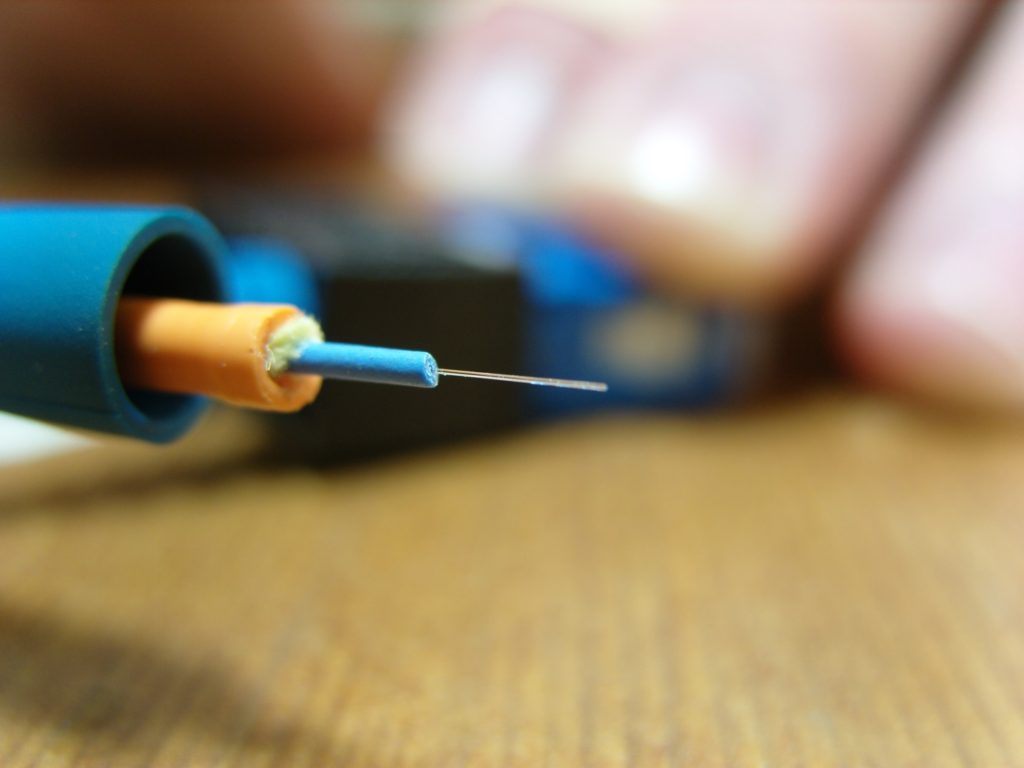
Before illustrating the suggestions for proper handling of optical fibers, a few kinds of fiber damage will be introduced, which are compressive damage, abrasive damage, fatigue damage and particulate penetration.
Compressive damage may occur when a fiber is pinched, clamped, or constrained to a point where the coating or glass layers become damaged. This can result in several effects depending on the severity of the compressive force, including coating delamination, coating damage (splits, cracks), and strength degradation due to the introduction of flaws onto the glass surface.
Abrasive damage may occur when a fiber comes into sliding contact with a sharp object such that it is scratched or scraped. This may result in damage of the polymeric coating or removal of it from the fiber. And it is also probably that the contact will damage the glass surface of the fiber, creating flaws that reduce the fiber's strength.
Fatigue damage is defined as the slow extension of a flaw over time due to the application of a tensile stress in the presence of moisture or humidity. The implication of fatigue is that a fiber may degrade in strength over time if placed under a considerable stress, which could be in form of a pure tensile, bending, or torsional stress, or any combination thereof.
Particulate penetration occurs when a hard particle, such as glass or ceramic, penetrates the coating layer of a fiber. This can often be initiated due to poor process cleanliness, and exacerbated by static electricity and subsequent processing.
To avoid those four kinds of fiber damages mentioned above as much as possible, there are corresponding practices.
- Never place tools, fixtures, or components on top of an optical fiber.
- Do not over-tighten objects used to constrain optical fiber.
- Avoid the use of tweezers or other such tools to handle optical fiber.
- Never allow a fiber to contact an uncontrolled surface where it may be stepped upon, rolled over with a chair castor, etc.
- If fiber is clamped during processing, ensure that the clamping pressure is limited so that damage is not induced. Any clamping materials that physically contact the fiber should be smooth, pliable and nonabrasive.
- Do not allow optical fiber to contact sharp or jagged edges or work surfaces.
- Take care with fingernails and jewelry when handling optical fiber.
- Never wipe an optical fiber with an abrasive material or with organic solvents such as acetone.
- Never allow an optical fiber to contact an uncontrolled surface where it may become snagged or otherwise abraded.
- Regularly check any pulleys or other hardware that the fiber may contact for nicks, burrs, corrosion, etc. All surfaces should be smooth and free of any debris or defect.
Always follow the recommended applied stress design guidelines for optical fiber. Generally, these rules dictate that an optical fiber should not be subjected to a stress higher than one-half the proof stress for a time on the order of one second, and to no more than one-third the proof stress for a time on the order of four hours.
- Clean all surfaces that contact the optical fiber regularly.
- Ensure that any bins or receptacles used to hold or contain fiber are free of debris.
- Never allow an optical fiber to contact an uncontrolled or dirty surface where it may contact particulate material.
- Check pulleys, work surfaces and other hardware regularly for the presence of corrosion or other contamination.
- Control static electricity, which may reduce fiber tangles, as well as attraction of particulate to the fiber.
- Do not cut or break optical fibers directly over work surfaces, which creates high stress fracture and may release numerous microscopic shards of glass over the work surface.
Proper handling of optical fiber can help you save a lot of money. These suggestions to reduce occurrences of fiber damage or breakage are applicable to a wide range of processes and applications. To create a functional and reliable product utilizing optical fiber, you can follow these guidelines in your handling and processing procedures.
How Much Do You Know About LC Duplex Connector?
There are many kinds of fiber optic connectors, such as LC, ST, SC, FC, MPO, MTRJ, etc. LC connector is one of the most commonly used connector type. Fiber optic jumper cables can be terminated with LC connectors on one end or both ends, like SC to LC cable, LC to ST fiber patch cable or LC to LC fiber patch cable. And there are LC to LC multimode simplex fiber optic patch cable and LC to LC multimode duplex fiber optic patch cable, for LC connector can be both simplex and duplex. LC duplex connector, the most well-known representative of SFF (small form factor) connectors, is widely adopted in fiber optic connectivity of today's LANs (Local Area Networks) and data center cabling. How much do you know about it? This blog will guide you to the world of LC duplex connector.
The standard LC connector, namely the traditional type, was developed by Lucent Technologies. It is designed with a retaining tab mechanism that is similar to the RJ45 connector. The body of a standard LC connector is a squarish shape, which is similar to an SC connector. Thus, LC connector is also called mini SC connector. Standard LC duplex connector is LC connector in a duplex configuration with a plastic clip. The ferrule of an LC connector is 1.25 mm. As the basic type, standard LC duplex connectors are universal in various fiber optic network applications.
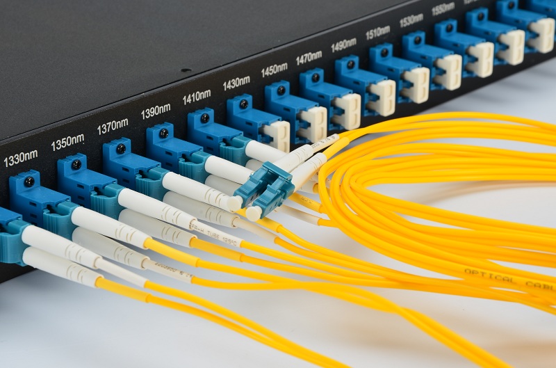
The LC duplex uniboot connector is two LC connectors encased in a common housing with one boot, terminated on a single twin-fiber round cable. This type of connector LC duplex connector is more compact compared to standard LC duplex connector. Fiber patch cables terminated with uniboot LC duplex connectors are ideal for high-density cabling applications, for they greatly reduce fiber counts and cable management space. And you need to know that the boots of an LC duplex connector can be configured with various versions according to different requirements. In addition to standard connector boots and uniboots, there are mini boots, BTW (Behind the Wall) boots, short boots, and 45 or 90 degree angel boots in the market.
If you have ever released LC duplex connectors from patch panels in high-density cablings, you might know how difficult it can be. In a high-density cabling, thumbs and forefingers have hard access to pulling connectors. LC-HD duplex connectors are ideal solution to this issue. With a flexible "pull-tab" or "push-pull tab", the LC-HD duplex connector can be disengaged easily from densely loaded panels without using special tools, which gives users easy accessibility in tight areas of high-density data center applications. And LC-HD duplex connectors with the uniboot design are more suitable to high-density cabling applications.
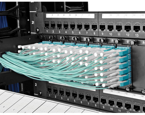
The mini-LC duplex connector is a variation of standard LC connector. It uses current industry-standard LC connectors but allows closer ferrule spacing by adopting the duplex clip (usually with color coding). Mini-LC duplex connector has a reduced center spacing of 5.25 mm compared to a standard LC duplex connector of 6.25 mm. This type of LC duplex connector is designed to operate with the Mini SFP modules and provides a higher density deployment for data center equipment.
Keyed LC duplex connector assemblies add more colors to the LC connector world as they use 12 color-coded keyed designs. Each color of keyed LC duplex connectors represents a unique keyed pattern. And each keyed design only allows its matched color-coded adapter to be mated. Keyed LC duplex connector can help to segregate or identify parts or paths within a network infrastructure, as well as to reduce the risk of accidental or malicious network access, particularly in shared access areas or in secure hierarchical environments.

There are many kinds of LC duplex connectors and, with the increasing requirements and the development of technology, there will be more new members to join the family. To choose the ideal type of LC duplex connector for your applications among all those types of LC duplex connectors, all you need to do is get a better understanding about them before making a decision.
What Are Simplex, Half Duplex and Full Duplex?
When talking about fiber optic jumper cables, such as LC LC multimode duplex fiber cable or LC SC single-mode simplex fiber optic patch cable, we came across simplex and duplex, or full duplex. What are simplex and full duplex? They are two kinds of communication channels in telecommunications and computer networking, which provide pathways to convey information. In fact, other than simplex and full duplex, there is another communication channel named half duplex. These three communication channels are commonly used in telecommunication networks.
A communication channel can be either a physical transmission medium or a logical connection over a multiplexed medium. The physical transmission medium refers to the material substance that can propagate energy waves, such as wires in data communication. And the logical connection usually refers to the circuit switched connection or packet-mode virtual circuit connection, such as a radio channel. With communication channels, information can be transmitted without obstruction. In this article, a brief introduction to these three communication channel types will be given.
A simplex communication channel only sends information in one direction. For example, a radio station usually sends signals to the audience but never receives signals from them, thus a radio station uses a simplex channel. And it is also commonly used in fiber optic communication. One strand is used for transmitting signals or for receiving signals. The good part of simplex mode is that its entire bandwidth can be used during the transmission.
![]()
In half duplex mode, data can be transmitted in both directions on a signal carrier but not at the same time. At a certain point, it is actually a simplex channel whose transmission direction can be switched. Walkie-talkie is a typical half duplex device. It has a "push-to-talk" button which can be used to turn on the transmitter but turn off the receiver. Therefore, once you push the button, you cannot hear the person you are talking to but your partner can hear you. An advantage of half-duplex is that the single track is cheaper than the double tracks.

A full duplex communication channel is able to transmit and receive data in both directions on a signal carrier at the same time. It is constructed by a pair of simplex links that allows bidirectional simultaneous transmission. Take telephone as an example, people at both ends of a call can speak and be heard by each other at the same time because there are two communication paths between them. Thus, using the full duplex mode can greatly increase the efficiency of communication.

A simplex fiber optic cable has only one strand of tight-buffered fiber inside the cable jacket for one-way data transmission. The aramid yarn and protective jacket enable the cable to be connected and crimped to a mechanical connector. It can be used for both multimode and single mode patch cable. For instance, single-mode simplex fiber optic cable is suitable for networks that require data to be transmitted in one direction over long distance. Different from simplex fiber optic cable, duplex fiber optic cable has two strands of fibers constructed in a zipcord style. It is often used for duplex communication between devices to transmit and receive signals simultaneously. Duplex fiber optic cable can be applied to all sorts of applications, such as workstations, fiber switches and servers, fiber modems and so on. And single-mode or multimode cable is also available with duplex cables.
To understand the operation of networking, you should at least know the concept of communication channels. Simplex, half duplex and full duplex are three modes of communication channels. Each one can be deployed for different applications. To make a cost-effective decision, you can choose the right fiber optic cable according to the channel mode that you need.
Fiber Patch Cable Solutions for Transceiver Ports Interconnection
Fiber optic jumper cables are designed to interconnect or cross connect fiber networks within structured cabling systems. They are commonly used in data centers to interconnect ports and transceivers that accept LC and MPO/MTP fiber optic connectors. There are a full range of cost-effective fiber optic patch cable solutions which can meet your demands now and for your upgrades in the future. In this post, we will demonstrate the high-speed fiber patch cable solutions for 10G, 40G, and 100G Ethernet transceiver ports interconnection.
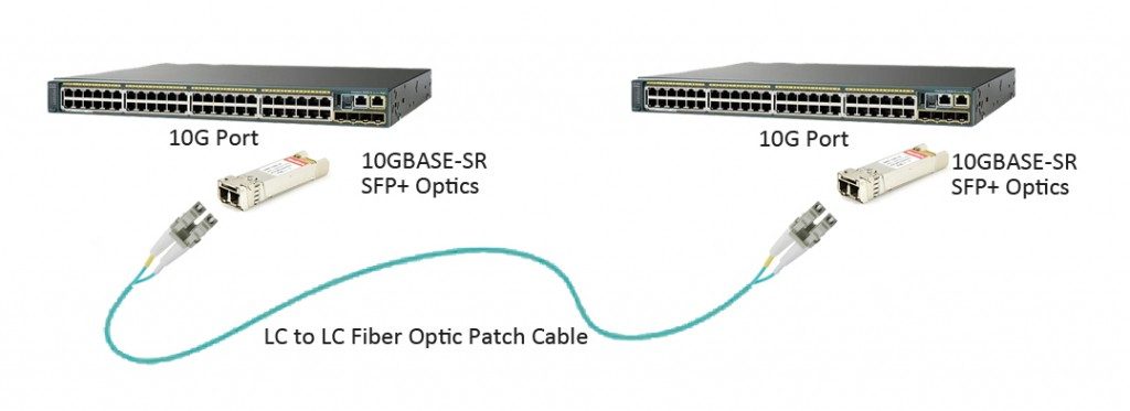
Today's data centers are still primarily architected around 10 Gigabit Ethernet (GbE). After almost ten years of revolution, SFP+ optical transceiver gradually becomes the main stream of 10G transceiver in data center optics market. According to the optical ports of SFP+ form factor, LC duplex fiber patch cable is required to complete the link between two SFP+ transceiver modules which are plugged into switches, routers or server NICs (Network Interface Cards), as shown in the following picture. High quality standard LC duplex patch cables are available in both single-mode and multimode versions, which are LC LC single-mode duplex fiber cable and LC LC multimode duplex fiber cable. With a wide range of material options, they can meet any working environment.
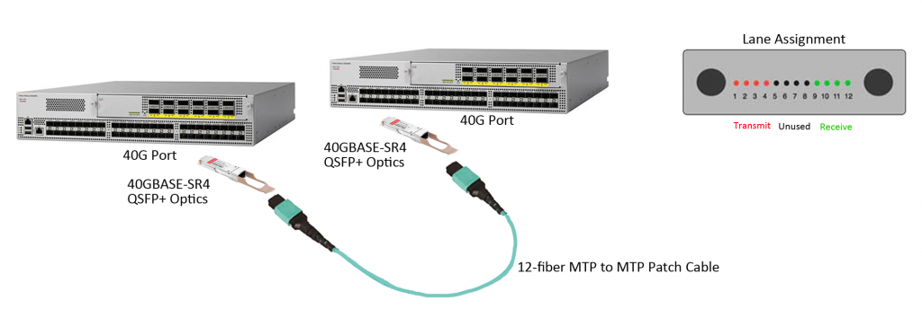
In recent several years, 40 GbE has gained more popularity and the market of 40GbE is encouraging. As data centers tend to deploy 40G Ethernet, 40G transceivers are ramping up. QSFP+ (quad small form-factor pluggable plus), as the most popular form factor for 40 GbE, has been widely used in data center switching fabrics. For the short reach interconnection between two QSFP+ optical transceiver ports, each QSFP+ module requires an MPO/MTP connection, as shown in the following picture. MTP to MTP (or MPO to MPO) assemblies can also be in single-mode or multimode versions, with jacket ratings of riser, plenum or LSZH. Users can easily upgrade their networks to future 40/100G applications with popular multimode OM3 and OM4 cable assemblies. Note: For single-mode 40G QSFP+ interconnection, duplex LC single-mode patch cable is commonly used; but for 40GBASE-PLRL4 QSFP+ interconnection, a 12-fiber MPO/MTP single-mode cable is needed.
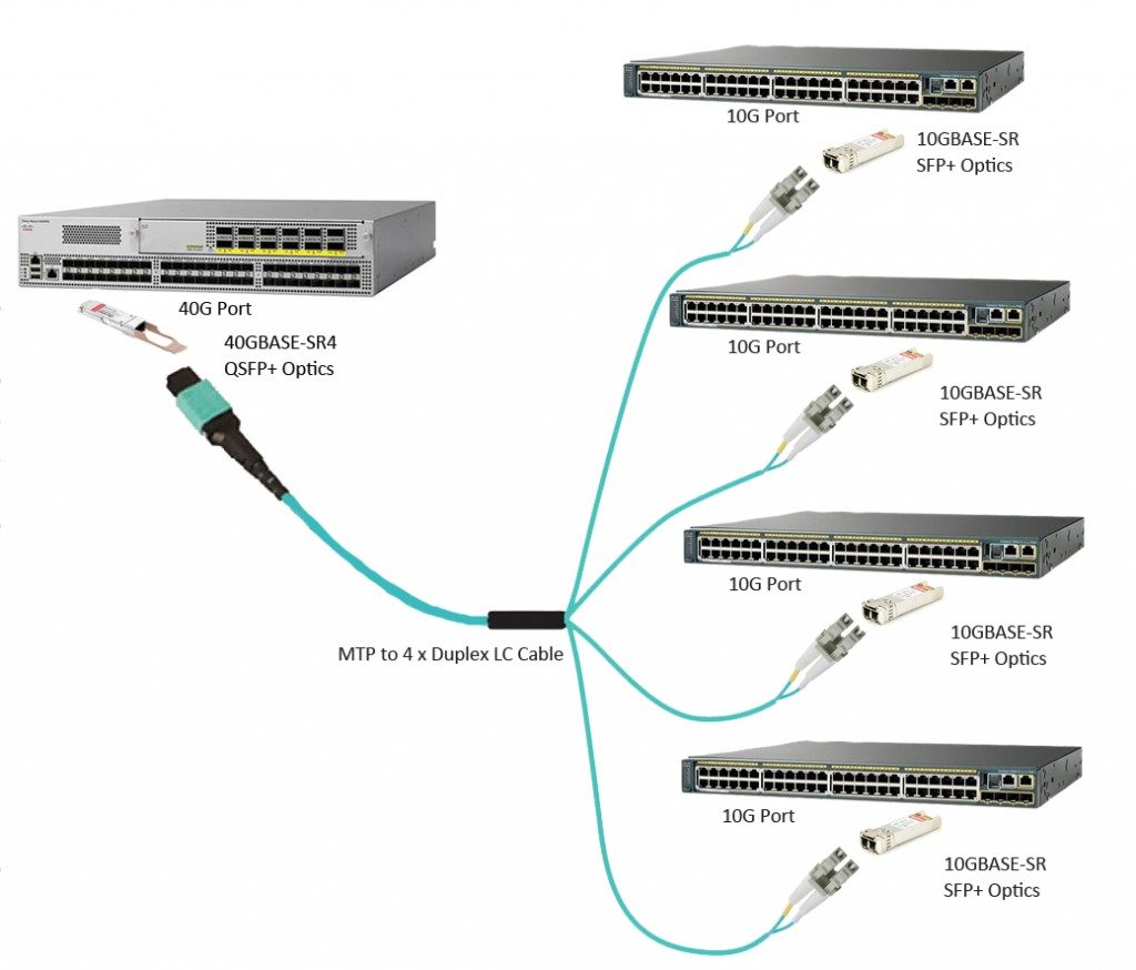
Other than the QSFP+ to QSFP+ connection, a single QSFP+ port (4 x 10 Gbps) can also breakout to four SFP+ ports, which is another interconnected solution for 40G transceiver. Using an MPO/MTP to LC assemblies, as shown in the following picture, can easily achieve the migration of 10G to 40G.
As the increasing bandwidth requirements of private and public cloud data centers and communication service providers, 100GbE has been growing rapidly and 2016 is considered as the year of 100G. Various 100G transceivers, such as CXP, CFP, CFP2, CFP4 and QSFP28 are available for different applications requiring data rates of 100G.
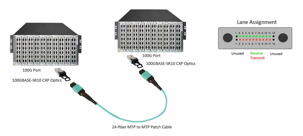
24-fiber MPO/MTP assemblies, implemented with 10 lanes of 10 Gbps, are ideal for 100GBASE-SR10 CXP/CFP to CXP/CFP interconnection in data center. Among the 24 fibers, only 20 fibers in the middle of the connector are used to transmit and receive signals at 10 Gbps and the 2 top and bottom fibers are unused. The picture below shows the interconnection between two 100GBASE-SR10 CXP ports.
QSFP28 optical transceiver has the exact same footprint as the 40G QSFP+ module, but QSFP28 is implemented with four 25Gbps lanes. To interconnect a multimode QSFP28 link, a 12-fiber MPO/MTP patch cable is required, but for a single-mode link (100GBASE-LR4 QSFP28), a duplex LC single-mode patch cable is required. The interconnection of QSFP28 multimode link is similar with the case of 40GBASE-SR4 QSFP+.
As mentioned above, 100GBASE-SR10 CXP/CFP module uses ten 10Gbps lanes to achieve 100Gbps data rate. Thus, a CXP/CFP port can be breakout to ten SFP+ ports using a 24-fiber MTP to LC harness cables, as shown in the following picture.
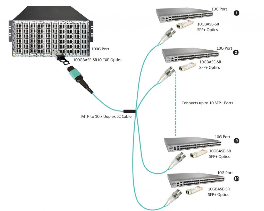
Bandwidth requirements have been increasing rapidly. To meet the bandwidth requirements, we move gradually from 10G to 40G and to 100G Ethernet networks. Equipment needed to achieve those bandwidths have also improved a lot. High-speed fiber patch cables are required for modern data centers. Different high-speed fiber patch cable solutions are available for your 10G, 40G, and 100G Ethernet transceiver ports interconnection. You can make the appropriate choices based on your needs and requirements.
Two Choices for FTTH Drop Cable Installation
Choosing the right drop cable interconnect solution is a crucial step for FTTH network deployment. It is for both ends of the drop cable—the distribution point and the home's optical network terminal (ONT) or the network interface device (NID). There are two choices: splices (permanent joint) and connectors (easily mated and unmated). These two options are both widely used at the distribution point, but at the ONT/NID, a field-terminated connector or a spliced-on factory-terminated connector would be a preferable choice. They both have their pros and cons. This post will discuss these two interconnect solutions for FTTH drop cables.
Pros: Splices can make sure excellent optical performance. Splicing can eliminate the possibility that the interconnection point becomes dirty or damaged. A dirty or damaged point may potentially compromise signal integrity, as may happen to a connector end face when it is handled while unmated. Contaminants will cause high optical loss or even permanently damage to the connector end face. And splice enables a transition from 250µm drop cable to jacketed cable.
Cons: Splice lacks operational flexibility. To reconfigure a drop cable at the distribution point, one splice must be removed, fibers rearranged, and new fibers spliced, which requires the technician to carry special splicing tools for simple subscriber changes. During this time, other customers' service may be disrupted by the fiber-handling process. 250µm fiber cable is usually used at the distribution point, which is easily bent and then causes high optical loss or even break the fiber. Besides, if a splice is used at the ONT, a tray is needed to hold and protect the splice, which increases the ONT size and potentially the cost.
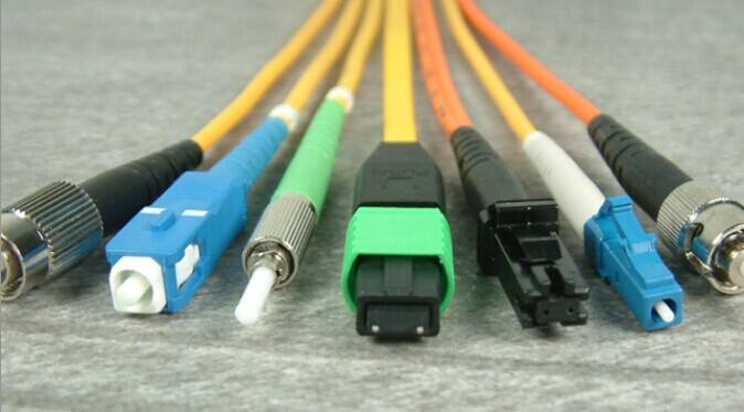
Pros: Connectors can be mated and unmated repeatedly, which makes them provide greater network flexibility. For example, to connect or disconnect an SC to ST fiber cable connection, without any tools, a technician can just easily plug or pull out the SC connector and ST connector on two ends. Connectors can also provide access points for networking testing.
Cons: Material cost is connectors' the most obvious downside. They cost more than splices, although network rearrangement with connectors is much cheaper. Providers need to weigh connectors' material cost and their potential for contamination and damage against the great flexibility and low network management expense.
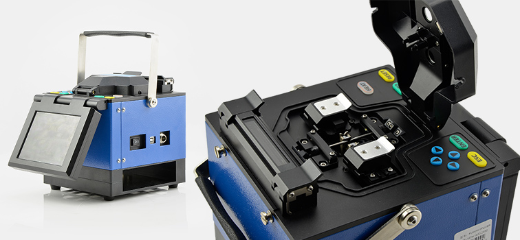
Splice is appropriate for drops where there is no need for future fiber rearrangement, typically in a greenfield or new construction application where all of the drop cables could be easily installed during the living unit construction. Once the decision goes to splices, the type of splicing (fusion and mechanical) must be determined.
Fusion splicing has been the de facto standard for fiber feeder and distribution construction networks. Fusion splicer is used for FTTH drop splicing as it provides a high quality splice with low insertion loss and reflection. However, the initial capital expenditures, maintenance costs and slow installation speed of fusion splicing hinder its status as the preferred solution. Fusion splicing is suitable for companies which have invested in fusion splicing equipment and have no need to purchase additional splicing machines. Mechanical splices are successfully deployed around the world in FTTH installation, but not popular in United States because the index matching gel inside the splices can yellow or dry out, resulting in service failures. Great strides have been made in improving gel performance and longevity over the last 20 years.
Connectors could be used to connect different subscribers as needed for distribution points. It must be installed at the ONT and then offers flexibility both at the curb and at the home. Once the decision goes to connectors, factory-terminated connectors or field-terminated connectors must be decided.
Factory-terminated cables, such as LC to LC cable or SC to LC cable, which means the connectors you specify are pre-terminated for you, provide high-performance and reliable connections with low optical loss. By reducing installation time, factory termination keeps labor costs low. But factory-terminated cables are expensive compared to field-terminated alternatives. And they require a cable management system to store slack cable at the curb or in home. The installation of field-terminated connectors can be customized by using a reel of cable and connectors. Fuse-on connectors use the same technology as fusion splicing to provide the highest level of optical performance in a field-terminated connector. Mechanical connectors provide alternatives to fuse-on connectors for field installation of drop cables. Depending upon service provider requirements and living unit configurations, a hybrid solution of a field-terminated connector on one end of the drop cable and a factory-terminated connector on the other may be the optimal solution.
Choosing the right drop cable interconnect solution is a key and important step for a successful FTTH network deployment. Making the right connection option will not only offer cost savings and efficient deployment but also provide reliable service for customers. Splices and connectors are two options for you. They have their advantages and disadvantages. A better understanding of them two can help you make a more suitable choice.
Optical Switch Overview
The rapidly growing optical networking technology has helped solve the problem of increasing demand for higher transfer data rates and bandwidths. Optical fiber is the fundamental medium of transmission in optical networks, but functions like switching, signaling and processing are accomplished electronically. To solve this problem and achieve conversions between optical signals and electrical signals, optical switches are naturally developed. How much do you know about optical switches? This post will offer some basic information about optical switches.
In telecommunication, an optical switch is a switch that enables signals in optical fibers or integrated optical circuits (IOCs) to be selectively switched from one circuit to another. An optical switch may operate by mechanical means, such as physically shifting an optical fiber to drive one or more alternative fibers, or by electro-optic effects, magneto-optic effects, or other methods.
An optical switch is simply a switch which accepts a photonic signal at one of its ports and send it out through another port based on the routing decision made. There are two kinds of optical switches, which are O-E-O (optical-electrical-optical) optical switch and O-O-O (optical-optical-optical) optical switch, also known as all optical switch. OEO switch requires the analogue light signal first to be converted to a digital form, then to be processed and routed before being converted back to an analogue light signal. OOO switching is done purely through photonic means.

Optical switches are widely used in high speed networks where high switching speeds and large switches are required to handle the large amount of traffic. Optical switches are likely used within optical cross-connects (OXCs). An OXC may contain a whole series of optical switches. OXCs are similar to electronic routers which forward data using switches. Optical switches can also be used for switching protection. If a fiber fails, the switch allows the signal to be rerouted to another fiber before the problem occurs. It takes an optical switch milliseconds to detect the failure and inform network and switch. Besides, optical switches can be utilized for external modulators, OADM (optical add-drop multiplexers), network monitors and fiber optic component testing. In early days, original optical transceivers were required to be plugged into these switches. Now third-party optical transceivers are produced to save the cost. As shown below, you can test the compatibility of a fiber optic transceiver, such as Avago AFBR-79EIPZ compatible QSFP+ transceiver, HP JD089B compatible 1000BASE-T SFP transceiver or HP J4859C compatible 1000BASE-LX SFP transceiver in an optical switch.

Optical switches have several advantages compared with electric switches. They can save room and power consumption significantly, about up to 92 percent space and 96 percent power. If power savings are translated into cost savings, it means 3 kw can be reduced for each rack, which can save carriers from expensive diesel power generators, rectifiers and batteries, and save monthly maintenance costs for these devices and the purchasing and maintenance of cooling equipment for these devices. Optical switches are more scalable and faster than electric switches. All-optical switches are protocol and bit rate independent, so transfer rates will not be affected by bit rate limitations of switching equipment.
Optical switches also have some disadvantages. Currently, optical switches can not realize the technology to store photonic signals as easily as electrical signals. But they can store signals using fiber delay lines, as light takes a certain time to travel through a certain length of fiber (200,000 km per second in silica), which means a 10000 bit frame traveling at 10Gb/s requires 200m fiber. That is both expensive and impractical. And once a signal is put through a delay line, it cannot be processed until it comes back out. A solution to this is adding switches within the lines, but that will increase the costs. Optical switches cannot process header information of packets, especially at high traveling speed. The maximum speed electronic routers currently can operate is 10Gb/s while optical signals can travel up to 40/100Gb/s or even higher. Thus, the routers will not be able to process the signals as fast as the transmission.
With the increasing demand for video and audio and challenges of data capabilities and high bandwidth of networks, optical networks have gradually become the most cost-effective solution. Optical switches can provide customers with significant power, space and cost savings. They are widely used in high speed networks where high switching speeds are required to handle the large amount of traffic.